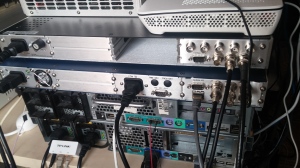
In an age when time synchronization is getting vital and faster (NTP) and more accurate (PTP – IEEE 1588 ) with increasingly high performance network protocols, there are still glorious time codes used to synchronize time reference units or clients on primary time and frequency standards .One of them it is the IRIG-B. Recently i found on ebay , (at really ridiculous price, considering the listing price of over 5000 Euros for a new unit! ) a Symmetricom XLi. As a natural evolution of its predecessor, the XL_DC , (also equipped with a disciplined TCVCXO ) , the XLi it is a great time and frequency receiver with many more capabilities such an ethernet port for remote administration and configuration, a built-in stratum 1 NTP server , a flash memory for remote software upgrades ,a Telnet access for a command-line based interface and SNMP . Symmetricom (now MicroSemi) declares 1×10-12 Frequency Accuracy with better than 30 Nanoseconds RMS Accuracy to UTC, wich are pretty awesome results for a TCVCXO , since we are not talking of a rubidium or cesium unit.
Another huge plus it’ s the rack unit with a modular, full customizable Plug-and Play capability to add any kind of modules like 10 MHz low noise output, FTM III to read phase and offset of the 50 Hz / 60 Hz powerlines. I’ve bought this unit clear, without any GPS module ( 87 8028 2 ), so i’ve tried to use in this case the IRIG-B time code, to provide a lock over the TCVCXO , using the IRIG-B output from the old unit, the XL-DC. (each unit can be a reader/generator of IRIG A,B and NASA 36 AM and DC.
So first of all, what is the IRIG-B , and how does it operate ? Here you can find the original documentation
Inter Range Instrumentation Group is the standards group of the Range Commanders Council, and amongst other things is responsible for the standard for IRIG Time Codes. The time code standard has been around for many years, and is still widely used for time communication between instrumentation systems worldwide. The most commonly used format is the IRIG B time code, due to it suitability in terms of precision and convenience (the 1kHz amplitude modulated version can be carried for several hundred meters over standard coaxial cable).
AM stands for “Amplitude Modulated” and describes the 1kHz sine, amplitude modulated version form of IRIG B. The more definitive description of this version, is IRIG B 120 wich i’m using on this model .
As you can see, the digital format of the IRIG-B000 as the leading edge of the first Marker pulse is well defined and can be generated to a few tens of nano seconds with a good source clock while the IRIG-B120 (The AM version) has a less well defined leading edge as it is a function of the sine wave “cross-over” point, and this limitation reduces the accuracy somewhat to around a micro second, although some manufacturers do inject a small “blip” on the first Marker pulse to assist with cross-over detection accuracy. From the “old” XL_DC unit IRIG output it is coming out the version B120, with AM modulation, i’ve tried to do a test putting on the oscilloscope the 1PPS output and the IRIG-B120 with a trigger on the 1PPS.
The frequency offset is computed using an averaging time that is equal to the effective averaging time of the oscillator controller. The oscillator Drift Rate is computed using a 24-hour average and is the daily Drift Rate of the oscillator. The oscillator DAC value is the signed 16-bit integer that controls the DAC output voltage. It ranges from 0 to 65536. Anyway these are the IRIG-B120 input specification for the Xli model :
The XLi first synchronizes to IRIG-B-120 w/ IEEE1344 when the Time Quality control bits are = 0000. The XLi remains synchronized (Locked) while the Time Quality control bits are 0000 through 0101 (ETE < 10uSec). The XLi utilizes the IRIG-B-120 BCD , IEEE1344 year, leap second, and leap second pending bit as the UTC epoch. The XLi time format selection remains on the XLi including the Daylight saving time offset.
For everyone is looking for a scalable, modular rack unit to have an great Time Frequency Standard for its own laboratory / office , i suggest those models, they can be found over internet in the used market for a very considerable price (200-700 $ depends on used conditions)


One thought on “IRIG-B and Symmetricom XLi Time & Frequency System”